HXGN17 40.5 high voltage vacuum ring network switchgear
Product Overview
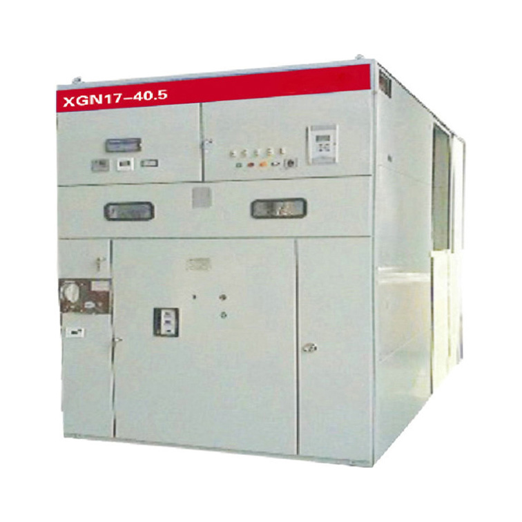
HXGN17-40.5 high-voltage vacuum ring network switchgear (hereinafter referred to as ring network cabinet) is a 50Hz AC three-phase indoor high-voltage power distribution equipment. It seals the load switch, grounding switch and the bus bar of the circuit together in a metal shell, adopts a spring operating mechanism, and uses SF6 gas as an arc extinguishing and insulating medium. It is suitable for ring network power supply or dual radiation power supply of 40.5kV power supply line, which can change the original single radiation power supply mode. When the line fails, it can restore the transformer loop feed in time, which greatly improves the reliability and utilization of power supply. It is especially suitable for industrial and commercial areas or rural towns with high power supply load density and cable feeder network. At the same time, the ring network cabinet is safe to use, not affected by the climate, easy to install, less maintenance, and saves space. It is very suitable for installation in box-type substations. , The load switch or load switch-fuse combination in the ring main unit can also be used as a separate cabinet.
Performance characteristics:
-
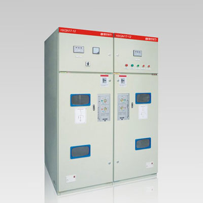
The ring network cabinet is composed of four parts: switch room, fuse room, operating mechanism room and cable room (underframe).
-
The switch room is composed of various functional circuits (including earthing switch and load switch) sealed in the metal shell and the bus bars between the circuits. The shell is welded by 3mm cold-rolled steel plate (or stainless steel plate). Each functional circuit includes a load switch and a grounding switch. The load switch is composed of a vertically moving moving contact system and a static contact at the lower end. When the switch is closed, the moving contact moves downward and the load switch is turned on. The grounding switch is composed of a moving contact knife and a static contact knife. During the spring movement, the grounding switch is quickly connected. There is a rectangular assembly process hole on the upper and rear parts of the switch room, and an observation window is installed on the front of the ring network cabinet, and the “open” and “close” positions of the grounding switch can be seen. An explosion-proof device is installed at the rear of the ring network cabinet.
-
The load switch adopts compressed air internal blowing structure, which has strong arc extinguishing ability and does not affect the phase-to-phase and ground insulation. The dynamic and static contacts are equipped with arc contacts, which greatly improves the number of breaking times.
-
The fuse and the load switch chamber constitute a transformer protection circuit. The high-voltage current-limiting fuse is installed in an epoxy-cast insulating shell. After the fuse is blown, the striker pops up and the load switch opens.
-
The operating mechanism room is located on the front of the ring network cabinet. In each functional circuit, the load switch is equipped with a manual (or electric) energy storage spring operating mechanism, and the grounding switch is equipped with a manual energy storage spring operating mechanism. There is a They are respectively used for the load switch closing operation and the manual opening rotary knob, the opening and closing operation holes of the grounding switch, the load switch opening and closing position indicator lights and the electric opening and closing buttons, and are equipped with analog lines and switch status Display plate and locked position, load switch and grounding switch are operated with interlocking device to prevent misoperation.
Order Notes:
The following technical information should be provided when ordering:
· Main wiring scheme number, purpose and single-line system diagram, rated voltage, rated current, rated short-circuit breaking current, layout diagram of power distribution room and layout diagram of switchgear, etc.;
· Requirements for switchgear control, measurement and protection functions, as well as requirements and schematic diagrams for other locking and automatic devices;
· The type, specification and quantity of the main electrical components in the switchgear;
When the switchgear is used in special environmental conditions, it should be specified in the order;
· Other special requirements must be explained and negotiated in detail before placing an order.
We welcome global agents, distributors, retailers, and other partners to join us and work together to develop mutually beneficial business relationships. Our products have already been well received by customers in many countries and regions, and we look forward to expanding our reach even further.