4.2 Terminal Application Wiring Diagram
Wiring Diagram for 0.75~37KW Variable Frequency Drives
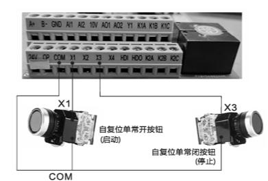
Explanation: Press the green button to start the VFD; press the red stop button to stop the VFD;
VFD parameter settings: P0-02=1; P4-02=3; P4-11=2
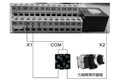
Explanation: Three-gear two normally open knobs, turned to the left for motor forward, turned to the middle for motor stop, turned to the right for motor reverse.
VFD parameter settings: P0-02=1
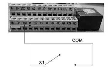
Explanation: Connect X1 terminal and COM terminal to start the VFD; Disconnect X1 terminal and COM terminal to stop the VFD; Direct power-on, power-off, directly short COM and X1.
VFD parameter settings: P0-02=1
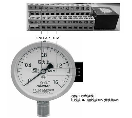
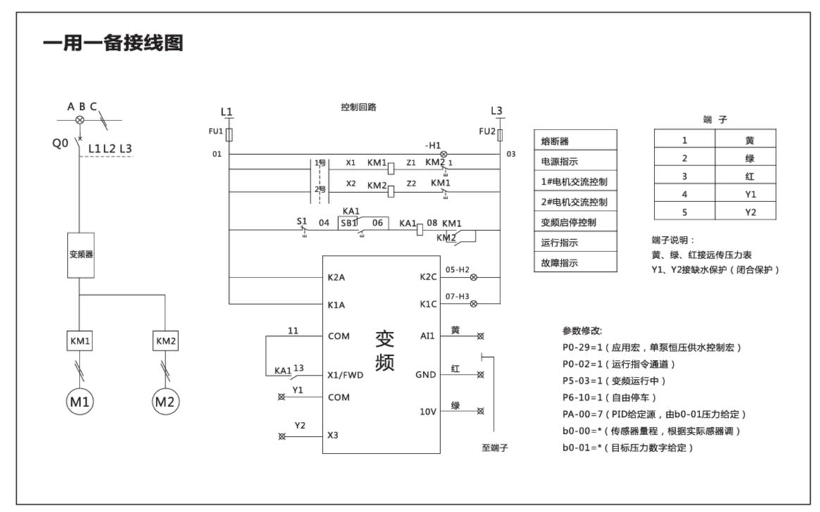
Explanation: The VFD serves as the core of the water supply system, able to monitor water pressure changes in real time and intelligently adjust the pump speed according to demand. When multiple users are using the water source simultaneously, the VFD will automatically increase the pump’s output power to maintain stable water pressure; while using smaller water flow rates, the VFD will decrease the pump’s output power to avoid excessive water pressure.
VFD parameter settings: P0-29=00001, b0-00=Pressure transmitter range, b0-01=Set pressure, b0-02=Sleep pressure, b0-03=Wake-up pressure;
Example: If the pressure transmitter range is 1MPA, b0-00=10, if the range is 1.6MPA, b0-00=16.
The upper line displays the set pressure, and the lower line displays the pressure transmitter feedback pressure. Adjust the set pressure using the 🔼/🔽 keys on the panel, with pressure displayed in kilograms. The upper line can switch between displaying bus voltage, current, frequency, set pressure, and feedback pressure using the ▶️ key.
🌟Note 1: After setting P0-29=00001, the default is external terminal operation. To start from the panel, set P0-02=0.
🌟Note 2: Settings for b0-02 and b0-03 are relative to b0-01 as a percentage.
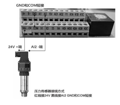
Explanation: The VFD serves as the core of the constant pressure water supply system, able to monitor water pressure changes in real time and intelligently adjust the pump speed according to demand. When multiple users are using the water source simultaneously, the VFD will automatically increase the pump’s output power to maintain stable water pressure; while using smaller water flow rates, the VFD will decrease the pump’s output power to avoid excessive water pressure.
VFD parameter settings: P0-29=00001, b0-00=Pressure transmitter range, b0-01=Set pressure, b0-02=Sleep pressure, b0-03=Wake-up pressure;
Example: If the pressure transmitter range is 1MPA, b0-00=10, if the range is 1.6MPA, b0-00=16.
The upper line displays the set pressure, and the lower line displays the pressure transmitter feedback pressure. Adjust the set pressure using the 🔼/🔽 keys on the panel, with pressure displayed in kilograms. The upper line can switch between displaying bus voltage, current, frequency, set pressure, and feedback pressure using the ▶️ key.
🌟Note 1: After setting P0-29=00001, the default is external terminal operation. To start from the panel, set P0-02=0.
🌟Note 2: Settings for b0-02 and b0-03 are relative to b0-01 as a percentage.
45~720KW Variable Frequency Drive Wiring Diagram
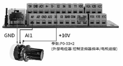
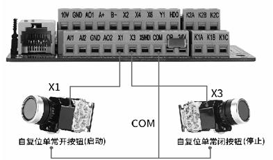
Explanation: Pressing the green button starts the VFD; pressing the red stop button stops the VFD.
VFD Parameter Settings: P0-02=1; P4-02=3; P4-11=2
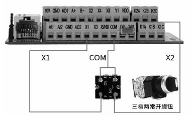
Explanation: Three-position toggle switch: Left position for motor forward, middle position for motor stop, right position for motor reverse.
VFD Parameter Settings: P0-02=1
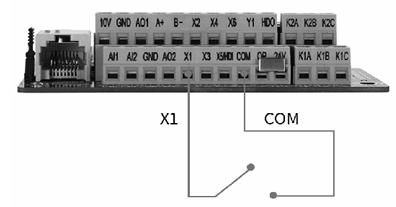
Explanation: Connecting X1 terminal to COM terminal starts the VFD; disconnecting X1 terminal from COM terminal stops the VFD; direct power-on starts, power-off stops, directly short COM and X1 terminals.
VFD Parameter Settings: P0-02=1
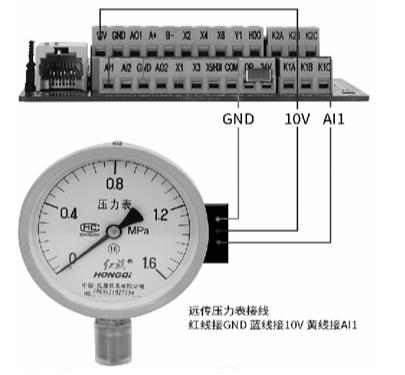
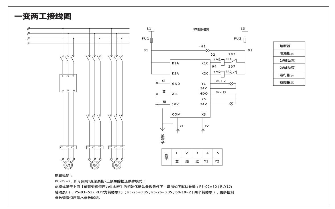
Explanation: The VFD serves as the core of the constant pressure water supply system, capable of monitoring water pressure changes in real-time and intelligently adjusting the pump speed according to demand. When multiple users are simultaneously using the water source, the VFD automatically increases the pump output power to maintain stable water pressure; whereas when a smaller water flow rate is used, the VFD reduces the pump output power to avoid excessive water pressure.
VFD Parameter Settings: P0-29=00001, b0-00=Pressure transmitter range, b0-01=Set pressure, b0-02=Sleep pressure, b0-03=Wake-up pressure;
Example: If the pressure transmitter range is 1MPA, b0-00=10, if the range is 1.6MPA, b0-00=16.
The upper line displays the set pressure, and the lower line displays the pressure feedback from the pressure transmitter. Adjusting the set pressure is done through the panel’s increase🔼/decrease🔽 keys, with the pressure displayed in kilograms. The upper line can be toggled to display bus voltage, current, frequency, set pressure, and feedback pressure using the ▶️ key.
🌟 Note 1: After setting P0-29=00001, external terminal operation is the default; to enable panel startup, set P0-02=0.
🌟 Note 2: Settings for b0-02 and b0-03 are percentages relative to b0-01.
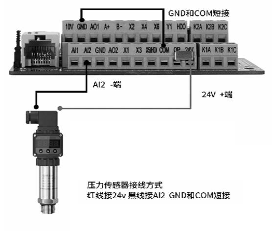
Explanation: The VFD serves as the core of the water supply system, capable of monitoring water pressure changes in real-time and intelligently adjusting the pump speed according to demand. When multiple users are simultaneously using the water source, the VFD automatically increases the pump output power to maintain stable water pressure; whereas when a smaller water flow rate is used, the VFD reduces the pump output power to avoid excessive water pressure.
VFD Parameter Settings: P0-29=00001, b0-00=Pressure sensor range, b0-01=Set pressure, b0-02=Sleep pressure, b0-03=Wake-up pressure;
Example: If the pressure sensor range is 1MPA, b0-00=10, if the range is 1.6MPA, b0-00=16.
The upper line displays the set pressure, and the lower line displays the pressure feedback from the pressure sensor. Adjusting the set pressure is done through the panel’s increase🔼/decrease🔽 keys, with the pressure displayed in kilograms. The upper line can be toggled to display bus voltage, current, frequency, set pressure, and feedback pressure using the ▶️ key.
🌟 Note 1: After setting P0-29=00001, external terminal operation is the default; to enable panel startup, set P0-02=0.
🌟 Note 2: Settings for b0-02 and b0-03 are percentages relative to b0-01.
Function Description of Multi-speed Command for SKF8000 Series General Purpose Variable Frequency Drive
There are 4 multi-speed command terminals, which can be combined into 16 states, corresponding to 16 instruction set values. Specifically, as shown in the table below:
| K4 | K3 | K2 | K1 | Instruction Set | Corresponding Parameter |
|---|---|---|---|---|---|
| OFF | OFF | OFF | OFF | Multi-speed 0 | PC-00 |
| OFF | OFF | OFF | ON | Multi-speed 1 | PC-01 |
| OFF | OFF | ON | OFF | Multi-speed 2 | PC-02 |
| OFF | OFF | ON | ON | Multi-speed 3 | PC-03 |
| OFF | ON | OFF | OFF | Multi-speed 4 | PC-04 |
| OFF | ON | OFF | ON | Multi-speed 5 | PC-05 |
| OFF | ON | OFF | ON | Multi-speed 6 | PC-06 |
| OFF | ON | ON | ON | Multi-speed 7 | PC-07 |
| ON | OFF | OFF | OFF | Multi-speed 8 | PC-08 |
| ON | OFF | OFF | ON | Multi-speed 9 | PC-09 |
| ON | OFF | ON | OFF | Multi-speed 10 | PC-10 |
| ON | OFF | ON | ON | Multi-speed 11 | PC-11 |
| ON | ON | OFF | OFF | Multi-speed 12 | PC-12 |
| ON | ON | OFF | ON | Multi-speed 13 | PC-13 |
| ON | ON | ON | OFF | Multi-speed 14 | PC-14 |
| ON | ON | ON | ON | Multi-speed 15 | PC-15 |
When the frequency source is set to multi-speed, the function codes PC-00 to PC-15 correspond to 100%, with PC-10 (maximum frequency) corresponding to 100%.
Explore these documents to learn more.